Swimming Pool Drown Detection and Rescue System (FYP)
#computer-vision #wearable #robotics #fullstack
A system that detects drowning incidents using a wearable device, pinpoints the location with computer vision, and deploys a robotic float for active rescue. I contributed to the concept, research, WebApp, and integration of the computation, wearable, and robotic components, as well as assisting in wearable development.
- Finalist, President's Cup 2022
- Nominated for ASM Technology Award 2022
Todo: Below is AI-genereated from the 3 report, waiting for review.
The problem
In Hong Kong, a shortage of lifeguards regularly closes pools and beaches, and the guards who remain are overworked. Poolside drowning accounts for 13% of all drowning deaths. The commercial systems we surveyed, Poseidon and SwimEye, watch the water with computer vision and raise an alarm once a victim is already sinking, so they need vast empirical datasets and still only buy time after the fact. The wearable alternatives fail for a different reason: RFID-based SwimTrack loses its signal beyond two metres underwater, and EDDS tracks pre-drowning heart rate but cannot say where the swimmer is, because 433MHz attenuates in water. Existing robotic responders, such as the Automated Underwater Lifeguard, navigate submerged and are too slow.
So we wanted a system that detects the pre-drowning physiological state, locates the swimmer through water using visible light, and actively delivers a float (a kickboard shot to the victim) rather than only notifying a human.
The sub-systems
The wearable is an Arduino Nano with a GY-MAX30100 pulse oximeter and four WS2812 RGB panel LEDs, powered by two 3.7V 18650 cells. Drowning is defined by physiological stage: panic and hyperventilation, then laryngospasm and hypoxemia, then loss of consciousness. The device watches for SpO2 falling below 90%. To keep a lost sensor contact from firing a false alarm, the reading must be abnormal on consecutive cycles before the alert flag is set and the LEDs begin their alternating red–green pattern.
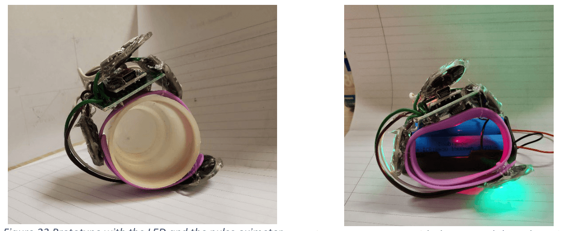
The wearable prototype, each PCB potted in silicone rubber. Right: the WS2812 panels lit.
The computation sub-system is a Python and OpenCV pipeline on an Ubuntu server, taking video from an Android phone running DroidCam as its webcam. It detects the pool corners by filtering for blue hues, running a Canny edge detector and taking the four intersecting lines from a Hough transform, warps that quadrilateral into a top-down view, then finds the blinking LEDs by multiscale template matching.
The robot is an Arduino Mega 2560 with an ESP01 WiFi module. A geared rotational base provides pan, a linear actuator provides tilt, and the shooting mechanism winds a spring along a V-slot aluminium rail and releases a PVC container holding the kickboard through a 12V relay lock. It aims to put a float in the water beside the victim within 20 seconds.
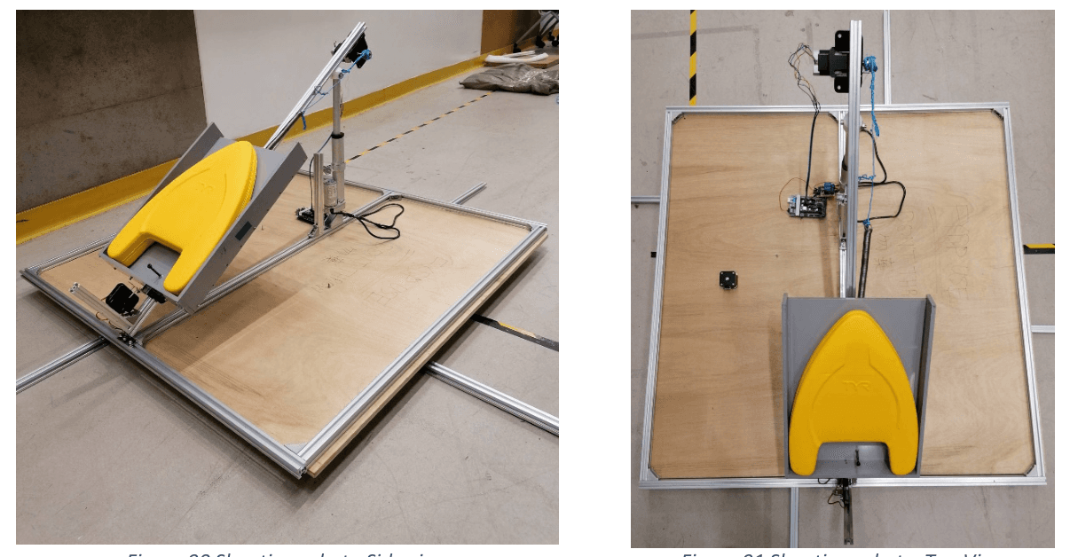
The launching robot: geared base for pan, linear actuator for tilt, spring along a V-slot rail to fire the kickboard.
System integration
The sub-systems themselves were straightforward compared to the seams between them: deciding what each boundary carries, in what format, and which side is master.
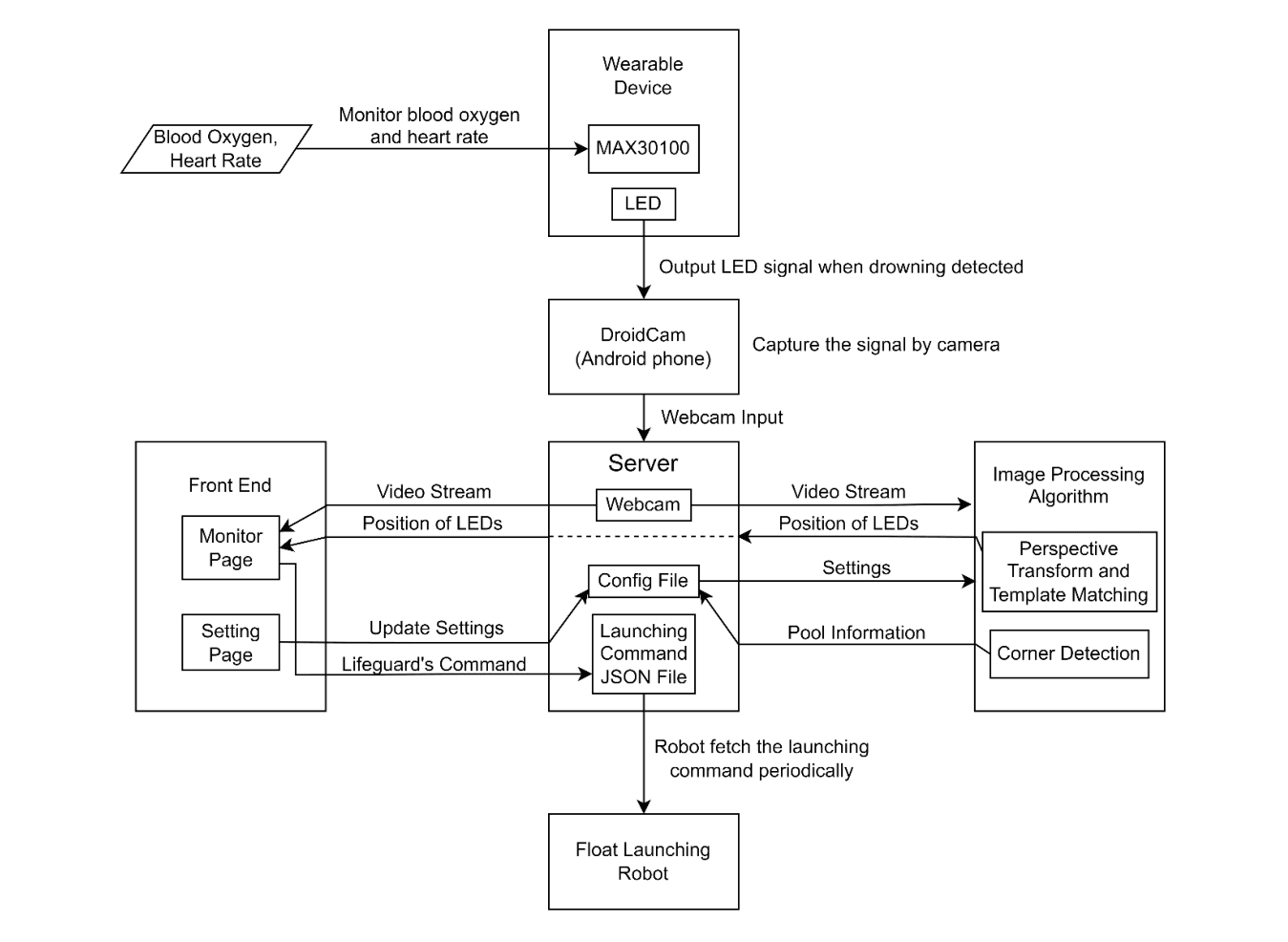
System architecture: four sub-systems and every link between them, with the server owning all state.
From alarm to kickboard
The path is deliberately short. SpO2 drops below 90% on consecutive cycles, and the Nano starts the LEDs alternating red and green at 135ms per colour. The webcam captures that, streams it to the server, and the OpenCV pipeline returns real-world pool coordinates. The web app raises the alert on the monitor page, marks the victim's position, and starts a ten-second countdown for the lifeguard. On confirmation, or when the countdown expires, the server solves the projectile motion, writes the firing parameters out, and the robot picks them up, aims, winds and shoots.
No link in the chain waits on a human, and every link degrades to something useful if the next one is unavailable.
The interfaces

The server's five interfaces, seen from the middle of the system.
Each boundary uses the cheapest transport that survives its environment.
Wearable to camera is visible light. The wearable emits and the camera receives, with no handshake, because none is needed. This is the one interface where the physics dictated the choice, discussed below.
Camera to server is WiFi over DroidCam, which let us treat a phone as a network webcam instead of building capture hardware.
Server to image processing is a language bridge. The server is node.js and the vision code is Python, so we bridged them with the child_process package: node spawns the Python program with arguments and reads the result back off flushed stdout. The pipeline exposes four functions, each called from a different place in the server's lifecycle: corner detection when the operator presses Auto in calibration, perspective transform when they submit the four corners, which writes the transformation matrix to a config file, LED detection on a loop from server start, and coordinate mapping when a shoot or aim command is issued. A helper re-reads the config files periodically, so a settings change takes effect without restarting anything.
Server to web app is WebSocket and HTTP. Express and EJS serve the interface, and socket.io streams frames as base64 image data to the client, which swaps them into an SVG image node's href as they arrive.
Server to robot is HTTP polling. The server writes shootingData.json containing angleH, angleV, velocity, shoot and note, and the ESP01 fetches it over HTTP and deserializes it into a StaticJsonDocument on the Mega. The server is master and holds all the state; the robot only ever reads.
A file plus an HTTP GET is not elegant, but it makes the robot stateless and trivially restartable. It can be power-cycled mid-incident and will resume from whatever the server currently wants, with no session to re-establish.
From pixels to a pool coordinate
The calibration chain turns a detection into an aiming command, and it passes through three frames of reference. The operator marks the pool's four corners once, or accepts the auto-detected ones, which fixes the perspective transformation matrix. A detection's image coordinates are mapped to physical pool coordinates by simple ratio against the known pool dimensions. The projectile motion routine then shifts the origin to the robot's deployment position, configured on the settings page because the robot does not always sit in the same place, and solves for the spherical polar angles the pan and tilt mechanisms need.
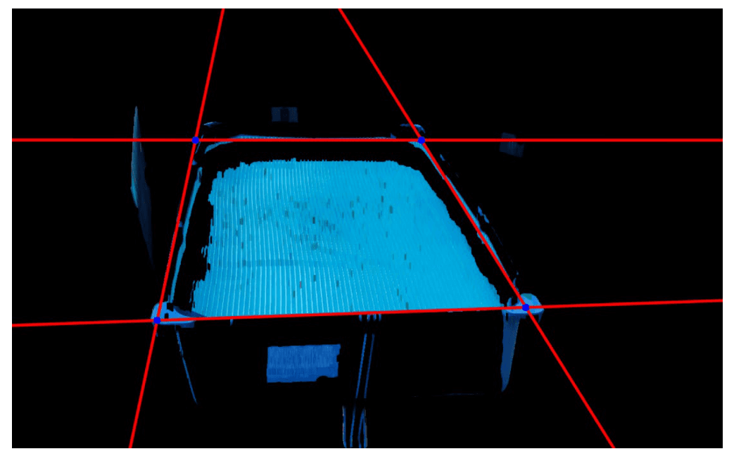
Corner detection: four Hough lines, and the intersections that become the pool's corners.
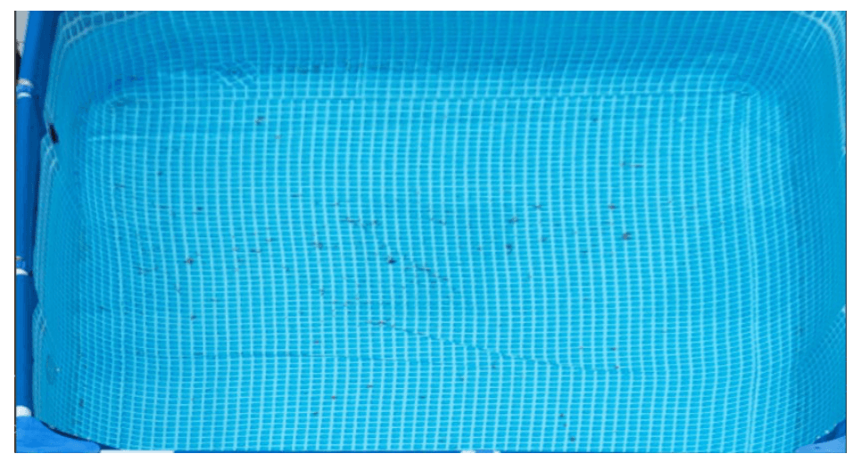
After perspective transformation: a top-down frame where pixel offsets map to metres by simple ratio.
Only the last step knows anything about the robot, and only the first knows anything about the camera.
The latency budget
We measured the chain by video-recording each event and timing it in an editor rather than trusting instrumented timestamps. From a real-world event to the local monitor takes 166ms, and in the worst case we tested, from home to HKUST and back, 433ms. The image analysis adds about 67ms on top of the webcam path. A shooting command reaches the robot in 66ms. So the system introduces roughly 0.3 seconds of delay and stays under half a second, which is enough for time-critical use.
Timing and concurrency
Two synchronisation problems surfaced between sub-systems rather than inside any one of them.
On the wearable, blinking the LEDs with delay() blocked the pulse oximeter's sampling, so the alert mechanism was starving the detector that triggers it. We rewrote the timing around millis() so the blink runs asynchronously against continuous sampling.
On the server, more than one swimmer can be drowning at once. A semaphore marks the primary target and queues the rest, each with its own ten-second decision window, so concurrent alerts serialise into a defined order instead of racing for the robot.
Failure modes
The integration layer, not the sub-systems, is where we handled the two failures that matter.
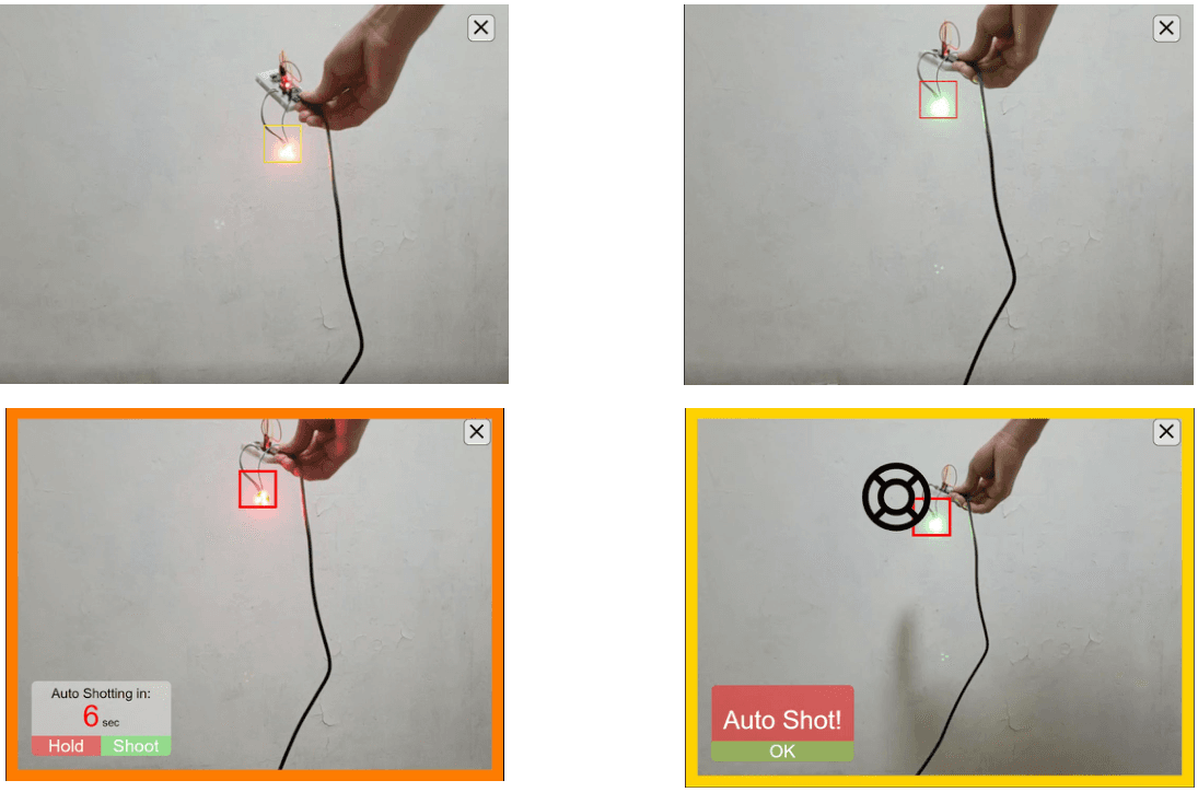
Alert escalation: the box warms from yellow to red with drowning duration, the countdown offers Hold or Shoot, and the confirmation persists until acknowledged.
If the lifeguard does not respond, the system auto-shoots after ten seconds. We would rather throw an unnecessary kickboard than miss a real one.
If the vision system misses the victim, the lifeguard can tap anywhere on the video stream. The tap enters the same mapping path an automatic detection uses and forces a dispatch, so the override stays short enough to trust.
Why visible light
Radio attenuates severely in water: 433MHz, Bluetooth and RFID all vanish within about two metres, and a sports camera I put underwater lost signal within one. Visible light penetrates furthest, drives easily at high power, and doubles as an alarm humans can see.
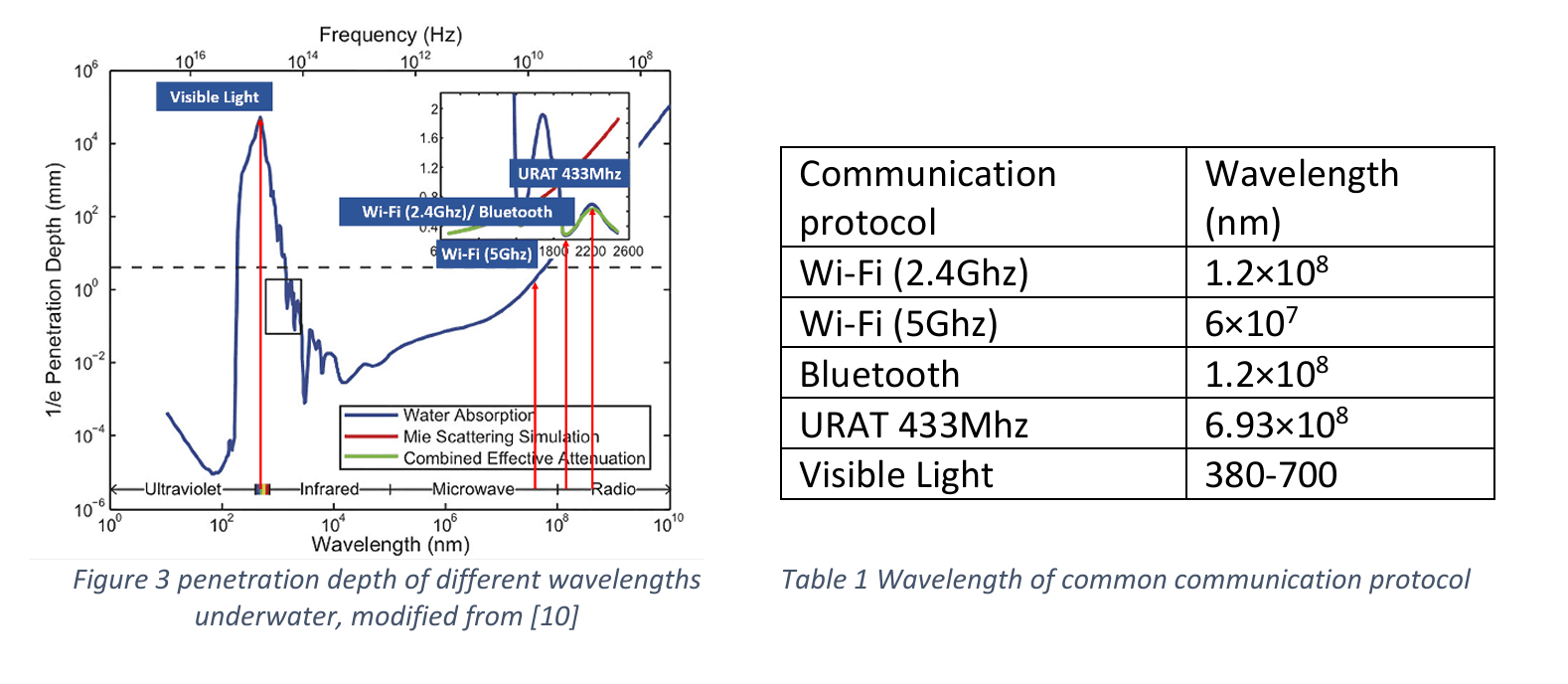
Penetration by band: visible light beats Bluetooth by about two orders of magnitude; UHF, used by RTK, is worst.
The blink rate is then set by the camera, not the water. At 30fps a frame is 33ms, so if the LEDs alternate too fast one exposure catches both colours and blends to yellow, which the template matcher discards. We tested 33ms, 67ms, 70ms and 133ms.
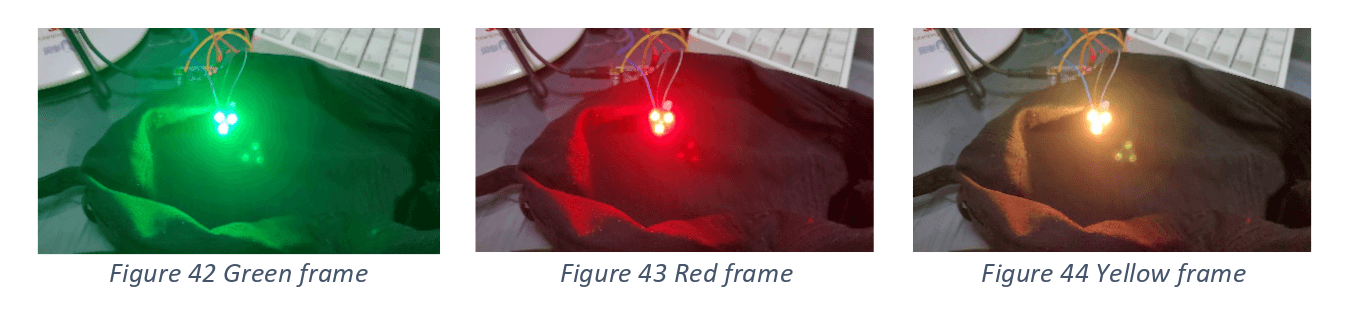
Green, red, and the blended yellow frame the matcher discards.
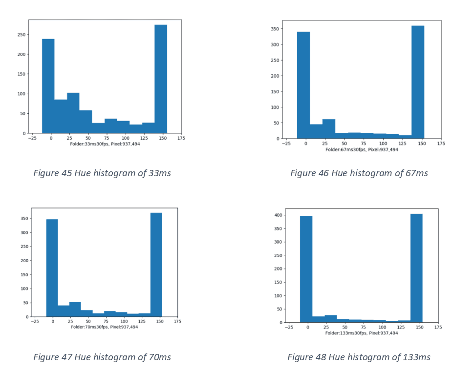
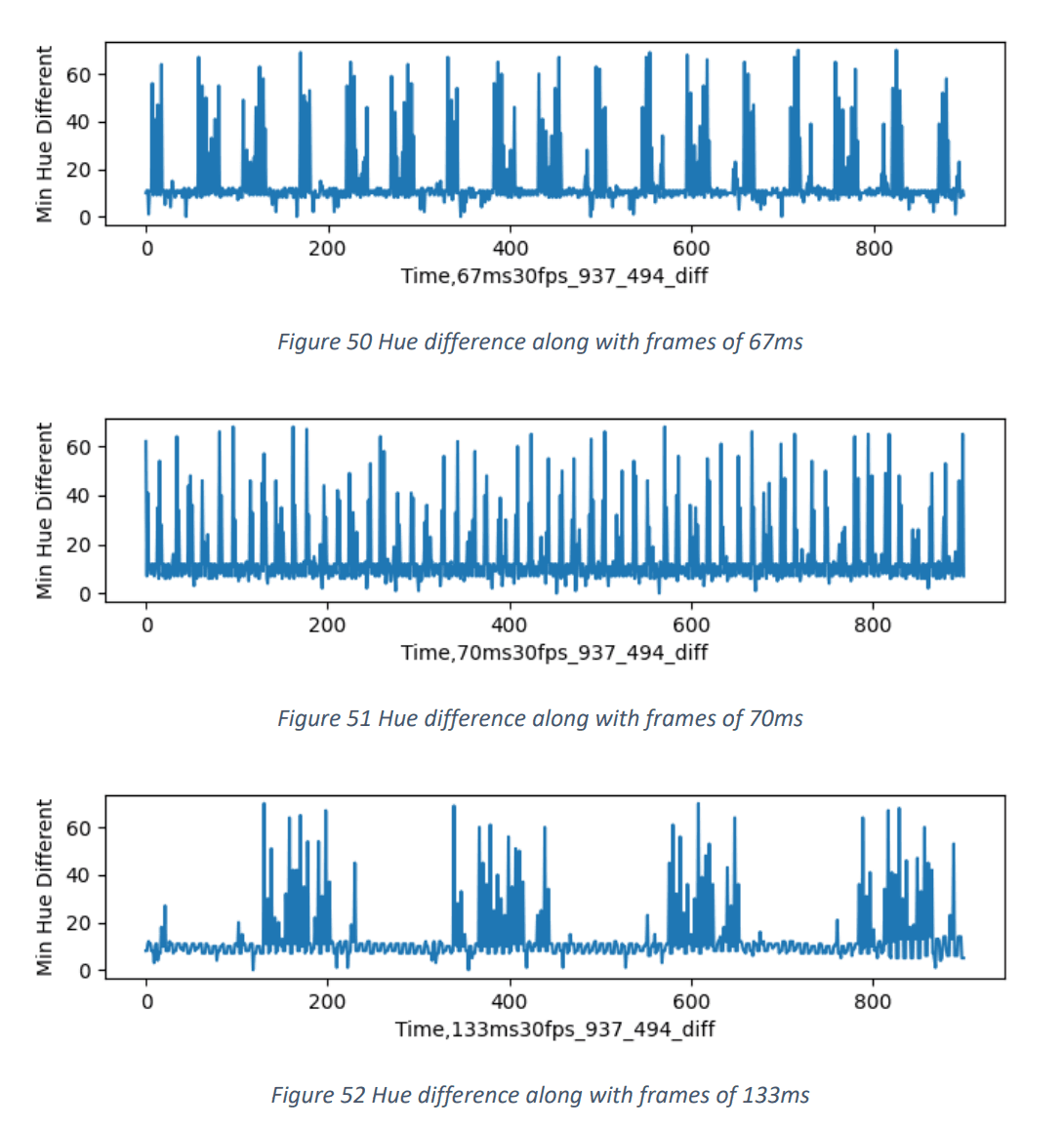
Left: hue histograms for the four rates, where the extremes are clean red and green. Right: hue error over time, one spike per yellow frame.
Rates near the Nyquist limit did worst. 67ms sits at a multiple of 30fps and its yellow frames bunch together; 70ms, only 3ms away, scatters them evenly.
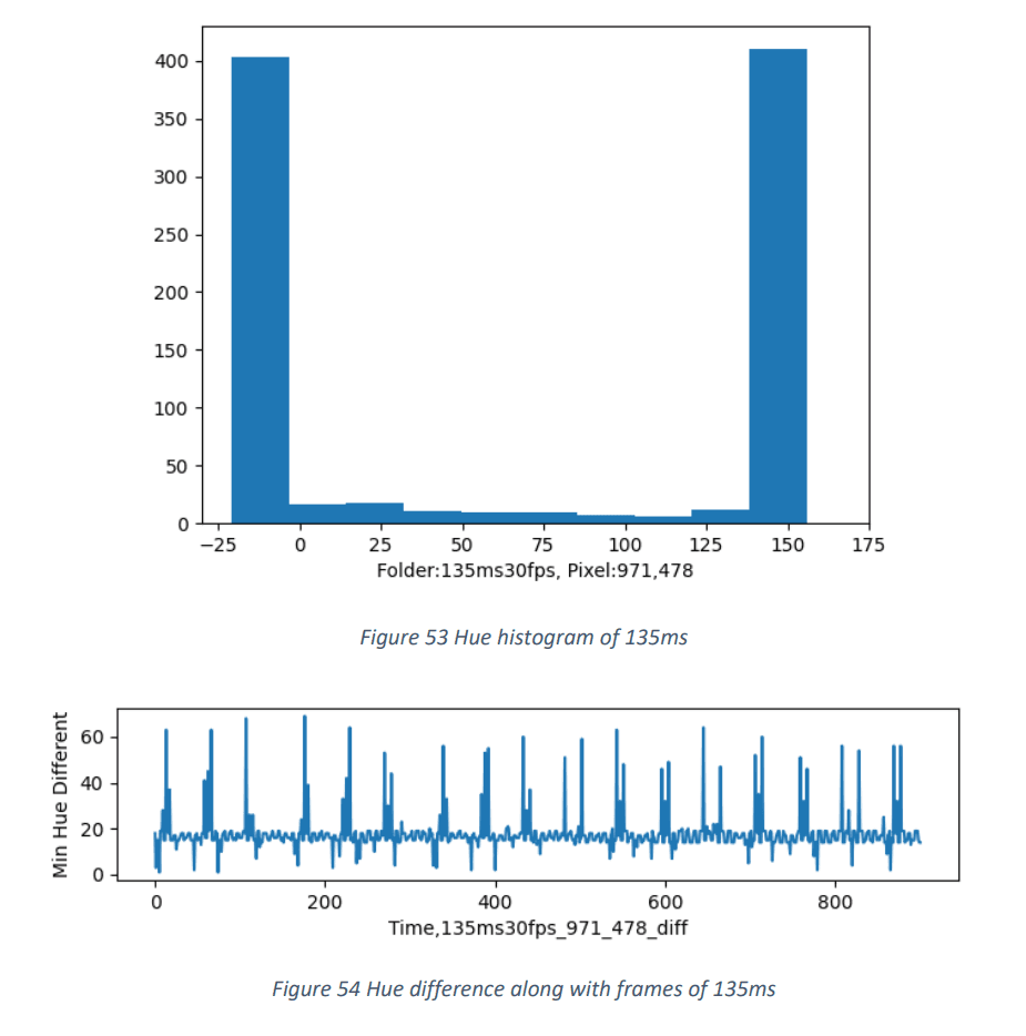
135ms won both experiments. In hindsight a prime interval such as 137ms was worth testing.
What integration testing taught us
COVID-19 closed the facilities, so the pool trials ran in a 2m by 3m test pool instead of a real one.
Most of what broke, broke at the boundaries. The wearable's first waterproofing attempt, a lock-n-lock box, leaked, so the final design potted each PCB individually in K-705 silicone rubber with only the USB serial port left exposed for debugging. Water-droplet tests failed to read the wrist at all until we moved the MAX30100 to the underside of the bracelet for tighter skin contact. The node-webcam package lagged badly on Windows 10, which is why the server runs strictly on the Linux VM. Even flashing the Nano needed the old ATmega328P bootloader and every peripheral wire disconnected before avrdude would sync.
Results and limitations
The MAX30100 read within 94–97% of a commercial fingertip oximeter when worn tight. Template matching located the LEDs with errors under 0.1m above the water surface and around 0.35m below it, the difference attributable to refraction. Every error was under 0.6m, one arm's length, so a kickboard shot to the detected position lands within reach of the victim.
The wearable is bulky, because supplying the LEDs at 7.4V demands two 18650 cells. The MAX30100 is designed for fingertips and the wrist is prone to motion artefacts. Corner detection can be fooled by large blue objects, such as the sky at a bad camera angle. Future work would move to a flexible PCB, swap in the wrist-optimised MAXREFDES103, consult biologists on the detection thresholds, and use the LEDs for real visible light communication, encoding heart rate, SpO2 and swimmer identity into the blink pattern instead of signalling a single bit of alarm.